Hardware
There are 4 steps for setting up the hardware:
1. WS2801 LEDs
2. Power Supply
3. Raspberry Pi GPIO
4. Mounting LEDs
1. WS2801 LEDs
2. Power Supply
3. Raspberry Pi GPIO
4. Mounting LEDs
Part 1 - WS2801 LEDs
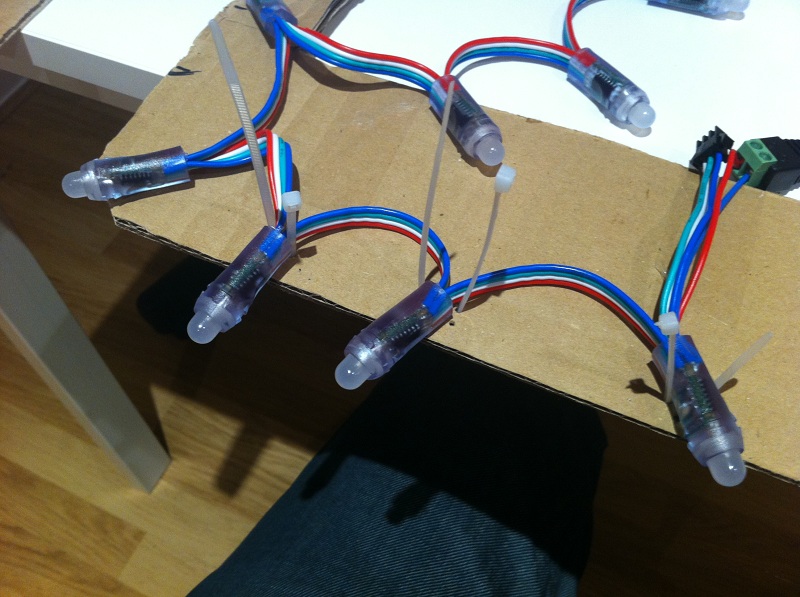
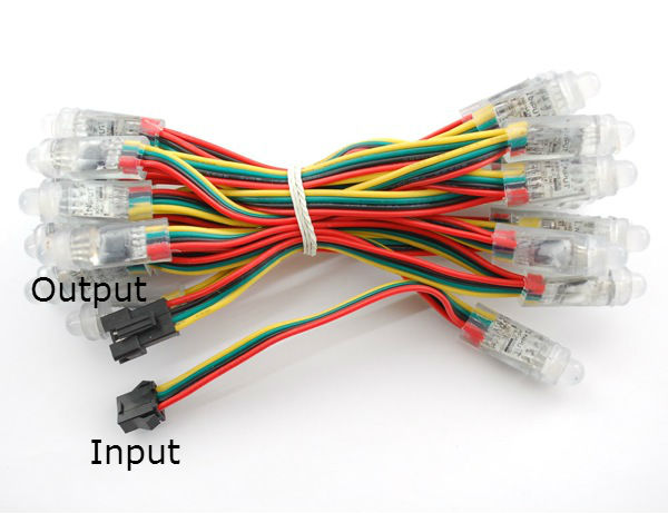 First thing you need to do is identify the input and output ends of your LED string.
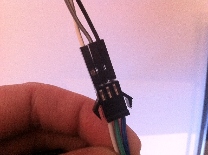
The input end will probably have a female plug on it (see image).
Once you have identified the input end you'll then need to work out which wire/colour is what. Since each supplier seems to use different colour wires, this can be tricky. You may be able to see through the LED casing and read what is printed on the circuit board.
Here's my wiring layout for reference, yours may vary:
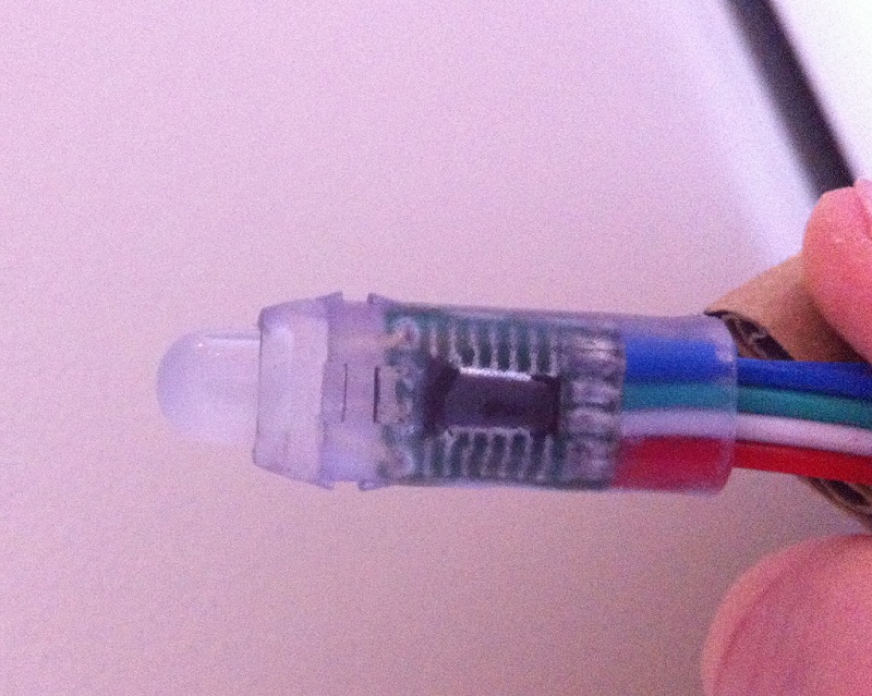
| Description | Wire Colour | Pin number | Pin Description |
| Ground | Blue | Pin 6 | Ground |
| Clock | Green | Pin 23 | SCLK |
| Data | White | Pin 19 | MOSI |
| 5V | Red | n/a | n/a |
You can also find some other wiring layouts here.
You should hopefully be able to identify 5V/GND easily enough, usually the first/last wires or you may find your power wires are split out from the female connector.
Once you have the power sorted, the other 2 wires can be figured out via trial and error which is pretty much what I did. Note: you don't need to do anything with the output end.
Part 2 - Power Supply
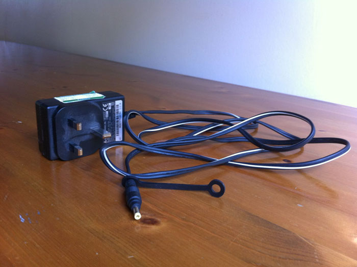
You could power your LEDs directly from the Raspberry Pi, but your Pi will probably become unstable and your LEDs will fade along the string as the Pi will struggle to supply the 1.5A max the 50 LEDs need (50 x ~30mA = 1.5A).
Therefore it is best to use a seperate power supply, i.e a 5v 2A transformer should do the job for 50 LEDs. (5v 5A should be enough for 100 LEDs)
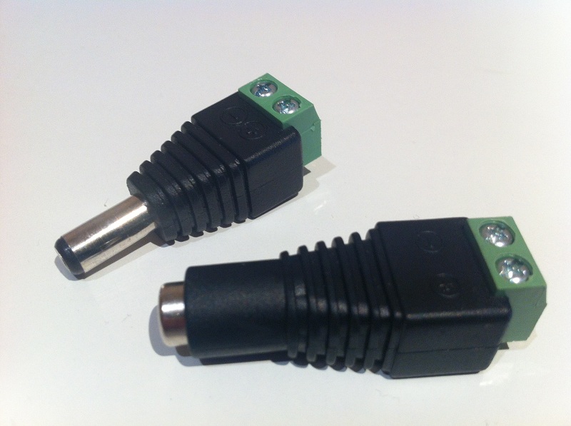
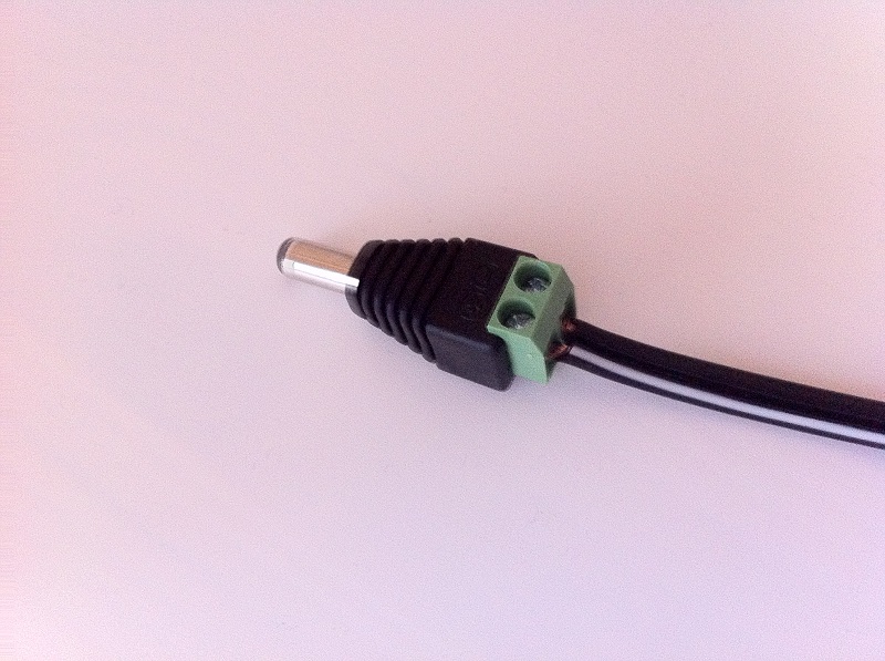
Unless you already have a matching female socket for your power supply it's best to use a CCTV male/female jack. You can get these on eBay for a few quid. Just cut off the existing plug on the power supply and attach the new male jack. Then attach the female end to the 5V/GND wires of your LEDs.
Therefore it is best to use a seperate power supply, i.e a 5v 2A transformer should do the job for 50 LEDs. (5v 5A should be enough for 100 LEDs)
Unless you already have a matching female socket for your power supply it's best to use a CCTV male/female jack. You can get these on eBay for a few quid. Just cut off the existing plug on the power supply and attach the new male jack. Then attach the female end to the 5V/GND wires of your LEDs.
 |
 |
 |
Part 3 - Connecting the LEDs to the Raspberry Pi GPIO
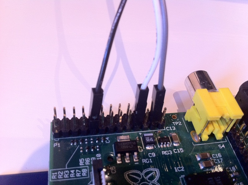
To connect the LEDs to the Raspberry Pi you will need some male to female jumper wires. Again, you can get these on eBay or Amazon pretty cheaply.
You'll need 2 for clock/data and possibly a third for ground. I found that with my LEDs only attached to ground via the power supply, they were flashing random colours and not working correctly until I hooked up the ground on the LEDs to ground on the Pi as well as the power supply.
You'll need 2 for clock/data and possibly a third for ground. I found that with my LEDs only attached to ground via the power supply, they were flashing random colours and not working correctly until I hooked up the ground on the LEDs to ground on the Pi as well as the power supply.
 |
 |
Part 4 - Mounting the LEDs
This step will largely depend on the type of LEDs you have and the type of TV you are mounting them on. Some LEDs come in strips which you can easily stick on with double sided tape.
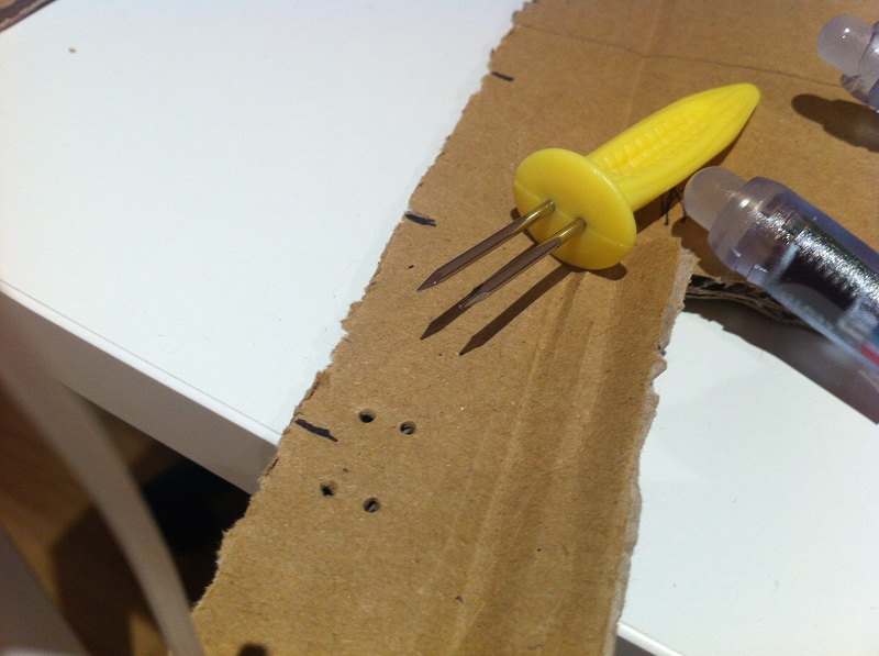
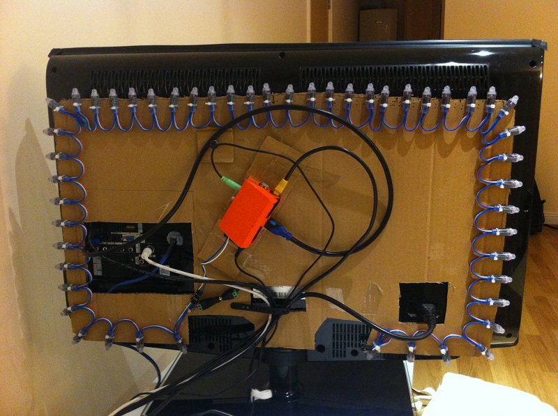
My LEDs are the bullet type so I decided to mount them on a board which I can then attach to the VESA mount of the TV. I decided to start with a rough prototype by cutting out some cardboard to the size and shape of my TV including holes for cables and any vents.
My LEDs are the bullet type so I decided to mount them on a board which I can then attach to the VESA mount of the TV. I decided to start with a rough prototype by cutting out some cardboard to the size and shape of my TV including holes for cables and any vents.
 |
 |
 |
I then divided up the 50 LEDs, measured and marked up the locations at even intervals. I made some holes either side of where the LED would be. I actually used one of those corn on the cob holder things, it worked really well actually! :)
You may notice I ordered the LEDs different to how I did in the software guide. The cables and wires fit better in this order, so I just edited my boblight.conf and reversed the order of the LEDs.
Once that was done I then zip tied all the LEDs in place and attached the Raspberry Pi. I was pretty happy with the results, the LEDs now give a nice even glow. Yes it is ugly, but this was just to test out my mounting method and also to give me a good template for a more permenant material. I will probably get a Pibow and a VESA mount too.
 |
 |
 copyright of
  is a trademark of the